
Circulation Pump Sets
Redundant variable-speed pumps supporting fault switchover and flow adjustment.
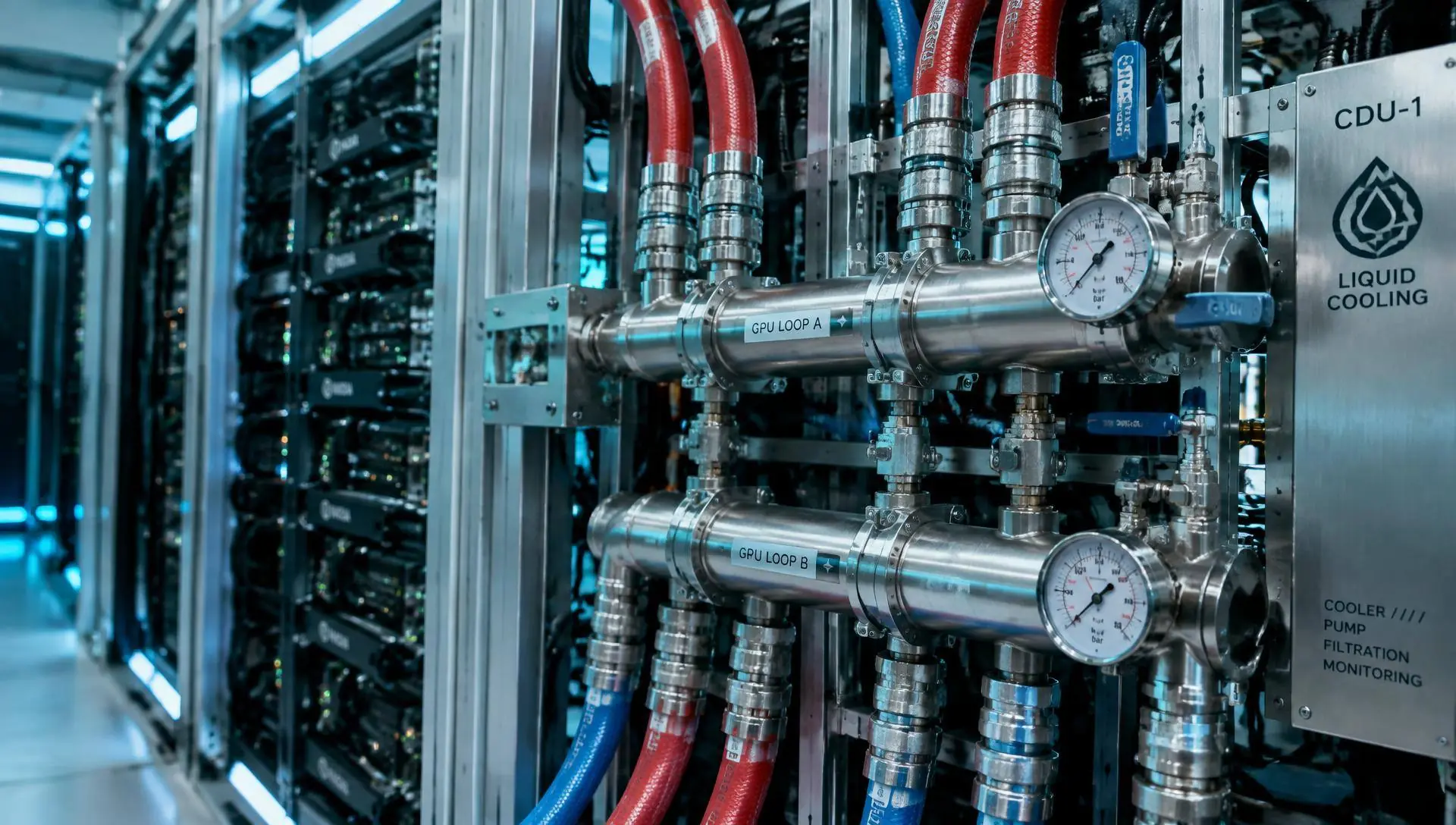
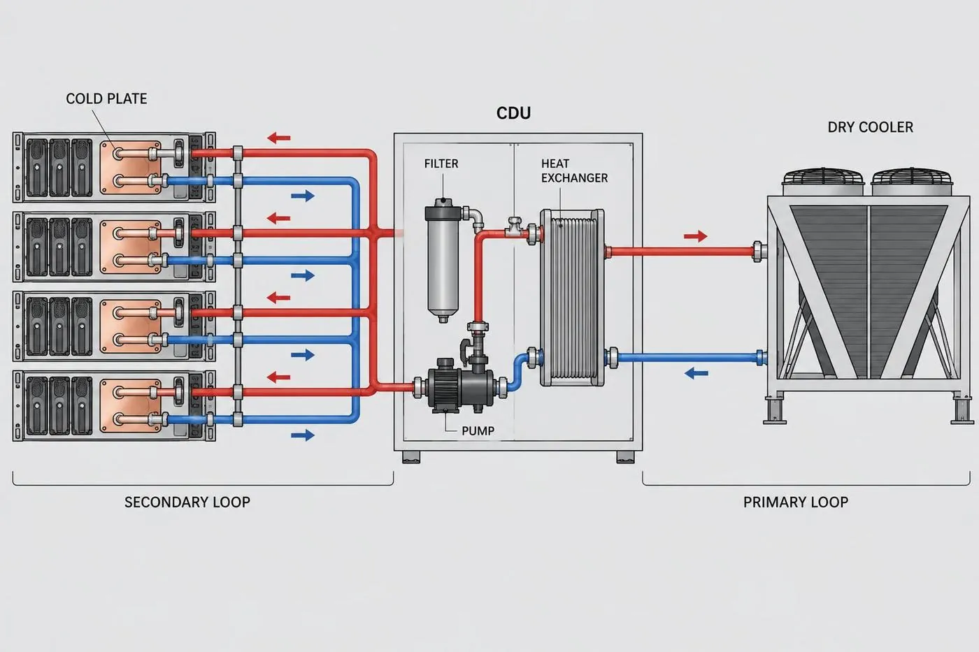
The cooling module uses a design separating the secondary and primary loops. The secondary side connects to the IT module's cold-plate piping, the primary side connects to outdoor heat rejection equipment, and the two are isolated by a plate heat exchanger, allowing water quality and pressure to be managed independently.
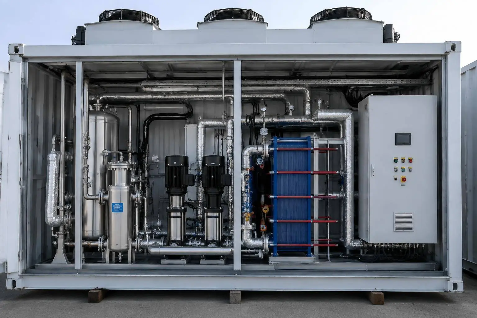
Pump sets are configured with redundancy, and together with filtration, make-up water and pressure monitoring devices, undergo interlock verification—including pump switchover and alarm logic—during factory testing.
The heat rejection side can be selected based on site climate and water resource conditions, with actual efficiency to be confirmed by project evaluation.
Key equipment and systems are factory-installed, piped and tested.
Redundant variable-speed pumps supporting fault switchover and flow adjustment.
Isolates the secondary and primary loops, easing independent water quality maintenance.
Side-stream filtration, make-up water and air venting devices ensure long-term loop stability.
Dry coolers or other heat rejection forms selected based on climate conditions.
Supply/return temperature, pressure, flow sensing points and isolation valves are factory-installed.
Local control and interlock logic, reporting operating data to the cluster control plane.
A quick look at how IT, cooling, and power modules differ and where each applies; specific parameters should be confirmed with site conditions and project evaluation.
| Dimension | IT MODULEIT Module | COOLING MODULECooling Module | POWER MODULEPower Module |
|---|---|---|---|
| Core role | Houses GPU racks, network equipment, and cold-plate liquid cooling piping — the direct carrier of compute capacity. | Collects heat from the IT side and rejects it outdoors, maintaining the temperature conditions equipment requires. | The complete chain from utility grid connection to rack power supply, ensuring continuity and metering of power. |
| Key components | Racks, cable trays and structured cabling, cold-plate manifolds, rack PDUs, environmental monitoring points. | Pump sets, heat exchangers, filtration and fluid make-up units, outdoor heat rejection equipment, water quality and flow monitoring. | MV/LV switchgear, transformers, UPS and batteries, busways and backup power transfer devices. |
| Key parameters to consider | Rack power density, number of racks, cooling method (cold-plate/air-liquid hybrid), network architecture. | Heat exchange capacity, supply/return water temperature and flow, free-cooling hours, PUE design target. | Incoming voltage level, total capacity, redundancy level, backup duration and transfer method. |
| Typical applicable scenarios | Added compute capacity, GPU platform upgrades, rack re-planning for training or inference scenarios. | High power-density liquid cooling deployments, free cooling in cold-climate sites, retrofits where existing cooling capacity is insufficient. | Access to renewable or hydro power, phased campus expansion, retrofits of existing facilities with limited power distribution capacity. |
| Interfaces with other modules | Connects to the cooling module's secondary supply/return water and the power module's busway feed, with unified monitoring integration. | Supplies water to the IT module, draws power from the power module, and feeds cooling capacity and water temperature data into monitoring. | Supplies power to the IT and cooling modules, with metering and protection data fed into monitoring. |
| Expansion approach | Add module units as compute demand grows, keeping the internal design of existing units unchanged. | Add pump sets and heat rejection units per thermal load, or add cooling modules. | Add power distribution units or increase incoming capacity as needed, releasing supply capacity in phases. |
Choose the loop configuration, heat rejection method, pump redundancy and temperature strategy to generate a recommendation summary and matching interface list.
Loop configuration: Heat-exchanger isolated (primary/secondary loop)
Primary and secondary loops are isolated by a heat exchanger, keeping IT-side water quality independently controllable — a common scheme for liquid-cooled clusters.
Heat rejection method: Dry cooler (air-cooled)
Dry coolers reject heat with essentially no water consumption, suited to water-scarce sites or where treatment costs are high; footprint and fan power should be accounted for in evaluation.
Pump redundancy: N+1
Pumps are configured N+1 so cooling continues during single-unit maintenance or failure — the recommended starting point for most training clusters.
Temperature strategy: Warm-water return (energy-efficiency priority)
Higher supply/return water temperatures extend free-cooling hours and lower annual energy use, subject to confirming allowable server operating conditions.
The above is directional guidance based on your selections; final capacity, equipment models and parameters need to be confirmed against site conditions and project evaluation.
The summary below covers the module's main interfaces and configurable range; the full "Interfaces & Technical Parameters" document (in Chinese) is available to download.
Determined by water-quality management strategy
Determined by site climate and water resources
Determined by availability target
Warm-water return can extend free-cooling hours
Includes isolation valves and measurement points
Includes bypass and drain valves
Treatment scheme determined by loop materials
Uploaded to the cluster control plane
Document No. XA-CL-IFC | Rev. A | Updated 2026-09
The document (issued in Chinese) covers module composition, external interface definitions, configurable ranges and on-site interconnection points, for design and engineering teams to review.
Download PDF (Chinese)Parameters in the document describe the configurable range; specific values need to be confirmed against site conditions and project evaluation.
The answers below are based on publicly available product information; specific parameters need to be confirmed against site conditions and project evaluation.
Need a solution and parameters for a specific site? Pleasebook a technical discussionor visit thefull FAQ pageto learn more.
Schematic and physical views side by side for engineering review.
The following parameters are determined during project evaluation based on site conditions and business scale.
Modules connect via standard interfaces, requiring no on-site redesign.