
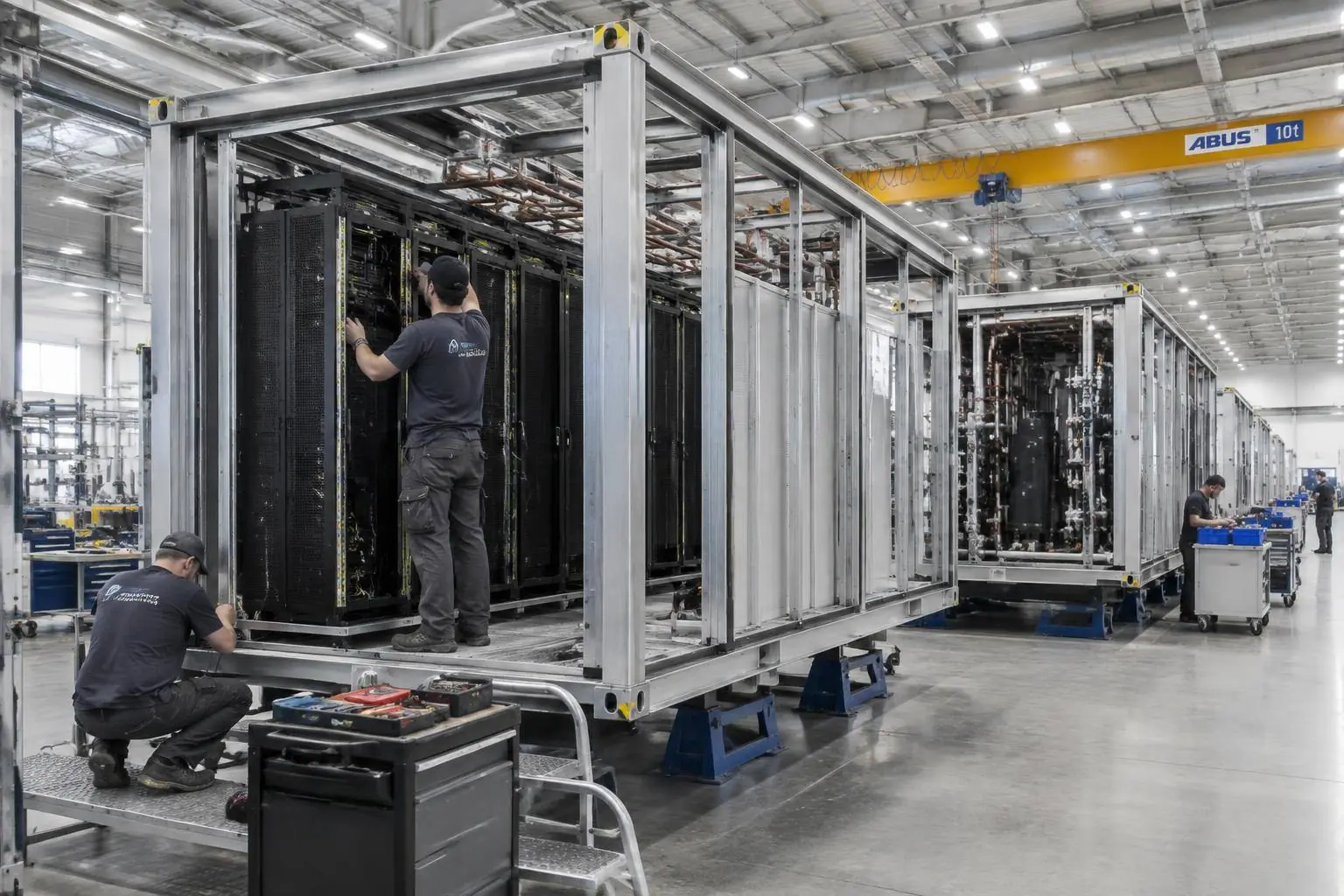
Choose a module to learn about
Each module has its own description of composition, interfaces, and configurable options.
IT Module
Houses GPU racks, network equipment, and cold-plate liquid cooling piping — the direct carrier of compute capacity.
View detailsCooling Module
Integrates pump sets, heat exchangers, filtration, and heat rejection equipment to move heat from the IT side outdoors.
View detailsPower Module
The complete chain from utility grid connection to rack power supply, including switchgear, UPS, and backup transfer.
View detailsComparing the three module types
A quick look at how IT, cooling, and power modules differ and where each applies; specific parameters should be confirmed with site conditions and project evaluation.
| Dimension | IT MODULEIT Module | COOLING MODULECooling Module | POWER MODULEPower Module |
|---|---|---|---|
| Core role | Houses GPU racks, network equipment, and cold-plate liquid cooling piping — the direct carrier of compute capacity. | Collects heat from the IT side and rejects it outdoors, maintaining the temperature conditions equipment requires. | The complete chain from utility grid connection to rack power supply, ensuring continuity and metering of power. |
| Key components | Racks, cable trays and structured cabling, cold-plate manifolds, rack PDUs, environmental monitoring points. | Pump sets, heat exchangers, filtration and fluid make-up units, outdoor heat rejection equipment, water quality and flow monitoring. | MV/LV switchgear, transformers, UPS and batteries, busways and backup power transfer devices. |
| Key parameters to consider | Rack power density, number of racks, cooling method (cold-plate/air-liquid hybrid), network architecture. | Heat exchange capacity, supply/return water temperature and flow, free-cooling hours, PUE design target. | Incoming voltage level, total capacity, redundancy level, backup duration and transfer method. |
| Typical applicable scenarios | Added compute capacity, GPU platform upgrades, rack re-planning for training or inference scenarios. | High power-density liquid cooling deployments, free cooling in cold-climate sites, retrofits where existing cooling capacity is insufficient. | Access to renewable or hydro power, phased campus expansion, retrofits of existing facilities with limited power distribution capacity. |
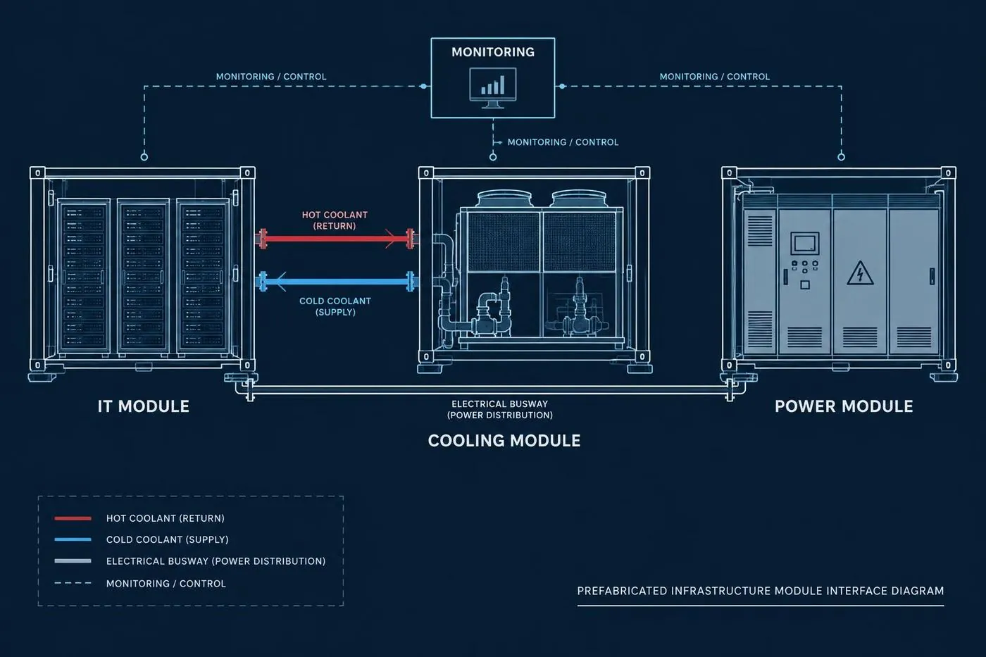
| Interfaces with other modules | Connects to the cooling module's secondary supply/return water and the power module's busway feed, with unified monitoring integration. | Supplies water to the IT module, draws power from the power module, and feeds cooling capacity and water temperature data into monitoring. | Supplies power to the IT and cooling modules, with metering and protection data fed into monitoring. |
| Expansion approach | Add module units as compute demand grows, keeping the internal design of existing units unchanged. | Add pump sets and heat rejection units per thermal load, or add cooling modules. | Add power distribution units or increase incoming capacity as needed, releasing supply capacity in phases. |
How the modules connect
Liquid cooling supply/return lines, electrical busways, and monitoring signals use standard interfaces, so on-site work only involves connection and verification.
Independently prefabricated
Each module is assembled and tested separately in the factory, shortening on-site work.
Standard interfaces
Liquid cooling, electrical, and monitoring interfaces are uniformly defined, making expansion and replacement easier.
Phased expansion
A base configuration can be deployed first, then module count increased as compute demand grows.